Solvent Extraction Equipment

Product Overview
The Solvent Extraction Equipment primarily consists of a leacher, steaming and desolventizing machine, evaporator, stripping column, condenser, and other key components. Utilizing the extraction principle of organic solvents, the process involves contacting, soaking, or spraying oilseed meal (such as soybeans) or pre-pressed cakes (e.g., rapeseed, cottonseed, sunflower seeds, peanuts, rice bran, sesame, tea seeds, coconut, etc.), enabling the efficient extraction of oil from the raw materials. This advanced process employs either a fixed-grid bottom rotary leacher or a circulating leacher made from stainless steel, along with stainless steel tube condensers, aluminum alloy tube condensers, or plate-type condensers, complemented by an exhaust gas refrigeration recovery unit. The technology is cutting-edge, delivering exceptional performance and reliability.
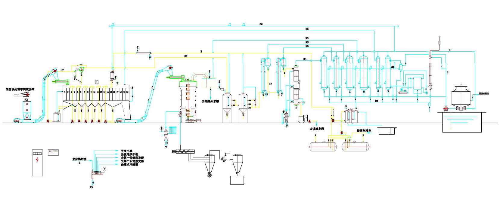
Leaching Production Line Process Flow

Process Flow Description of the Leaching Production Line
The cake blocks delivered from the oil-extraction workshop are fed into the leaching unit via an inlet scraper conveyor, which then transfers them to the feed-sealing screw conveyor inside the leacher. As the material moves through the leacher—from the inlet to the outlet— it completes a full circular cycle. During this process, the material is repeatedly sprayed and immersed with mixed oil of gradually decreasing concentration, finally receiving a fresh solvent spray. After passing through a draining section where excess liquid is allowed to drip off, the material is continuously discharged from the leacher and transferred to the wet-pomace scraper conveyor. Meanwhile, the most concentrated mixed oil is pumped by the concentrated mixed-oil pump into a hydrocyclone separator for impurity removal, before being temporarily stored in the mixed-oil tank.
The leaching unit contains wet meal, which is fed from the wet meal scraper via a material-sealing screw conveyor into the pre-dehydration section of the steaming and drying machine. The bottom section is indirectly heated with steam to remove part of the solvent from the meal. After pre-dehydration, the wet meal moves into the main steaming and solvent-extraction zone, where an automated system maintains a consistent material layer height. Direct steam is introduced at the bottom to completely strip out the remaining solvent, after which the meal flows into the cooling section to reduce its temperature. Finally, the finished meal is transferred to the meal storage bin.
The mixed oil is pumped from the mixed-oil tank into the tube side of the first long-tube evaporator via a feed pump. After being separated in the first-stage flash drum, the concentrated mixed oil then enters the second long-tube evaporator for further evaporation. The solvent vapor generated in both the first and second evaporators is directed to the evaporative condenser. Meanwhile, a portion of the mixed oil exiting the second flash drum is fed into the top of the stripping column through a heater, using a stripper feed pump. The temperature of the mixed-oil heater is automatically regulated by a control system. The mixed oil flows downward through the trays inside the stripping column, while direct steam is introduced at the bottom of the tower, moving upward in countercurrent flow. This ensures thorough contact between the vapor and liquid phases, effectively removing any residual solvent from the oil. At the bottom of the column, a level controller maintains an optimal liquid seal, ensuring stable product flow. Finally, the crude oil is drawn off from the bottom of the stripping column, preheated via heat exchange with the first-stage mixed oil, and then sent directly to the refining workshop.
The solvent, after being condensed by the condensation system, enters the integrated solvent storage tank, where it is separated from water before being recycled. The off-gases—originating from the leacher condenser, DT condenser, water separator, and circulating solvent tank—are all routed to the air-balancing tank, where they undergo final condensation to recover the solvent. Any non-condensable gases (tail gas) are then passed through a refrigeration unit for solvent recovery before being safely released into the atmosphere.
Leaching Process Flowchart