Continuous refining

Product Overview
The refining system consists of equipment such as a refining pot, decolorization and drying pot, deodorization pot, soapstock pot, crystallization tank, filter, heat-transfer oil furnace, vacuum system, and refrigeration unit. Crude oil undergoes processes including degumming, deacidification, decolorization, dewaxing, and deodorization to produce oils ranging from Grade 1 to Grade 4.
The equipment is available in intermittent (below 50 T/D), semi-continuous (20–80 T/D), and fully continuous (above 30 T/D) models. Users can select the appropriate process and equipment based on their production scale and desired oil quality standards.
Streamlined Production Line Process

Detailed Process Description of the Lean Production Line
Degumming and alkali refining >>
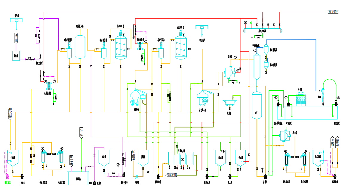
After being filtered to remove impurities, the crude oil is pumped from the crude oil storage tank into an energy saver and a plate-type heater, where it is heated with low-pressure steam to a specific temperature. The heated oil then flows into an acid mixer, where it is thoroughly blended with a precisely measured ratio of phosphoric acid solution. From there, the oil moves into an acidification tank for further acidification and conditioning—during this process, non-hydrated phospholipids in the oil are converted into hydrated phospholipids, facilitating their eventual removal. Next, the acidified oil is transferred to an alkali mixer, where it’s combined with another controlled amount of alkaline solution before entering a delayed-action reaction tank. Afterward, the oil is pumped through a heater to reach the desired temperature, after which it proceeds to a de-saponification centrifuge for oil-soap separation. The resulting soap sludge is first collected in a soap sludge tank for temporary storage, then later pumped out of the facility via a soap sludge pump for off-site storage. If the crude oil initially has an excessively high acid value, the de-saponified oil must undergo a second round of alkaline refining: It’s reintroduced into a highly efficient second-stage alkali mixer, where it’s thoroughly mixed with a precise amount of liquid alkali, before finally being sent to a second centrifuge for oil-soap separation.
After degreasing, the oil enters a water-washing mixer, where it is combined with hot water at a specific ratio. A portion of phosphoric acid solution is also added to effectively remove residual soap and other impurities. The mixture then moves into a water-washing centrifuge for further separation, ensuring that any remaining soap residues or unwanted particles are thoroughly eliminated. Finally, the purified oil is transferred to a vacuum dryer to remove moisture and other volatile substances, after which it is pumped directly to the decolorization section.
Decolorization Section >>
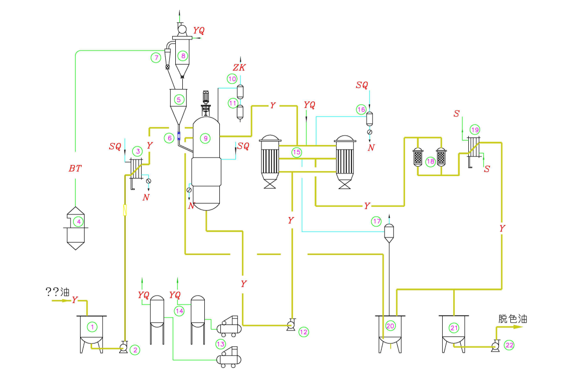
Decolorization is the process of removing colored substances from oil, typically achieved by mixing the oil with an appropriate amount of decolorizing clay, which adsorbs the pigments and separates them from the oil during filtration. The decolorizing clay is stored in a feeding hopper and then conveyed via an air-assisted system into the clay silo located above it. A pulse dust collector and a dust removal fan positioned atop the silo clean the air before releasing it back into the atmosphere.
The alkali-refined oil is heated by an energy-saving device and a plate-type heater before entering the vacuum pre-mixing tank, where it is blended with a specific proportion of clay. The clay is metered precisely by a dedicated quantitative system before being added. After pre-mixing, the oil flows by overflow into the decolorization tower.
The continuous decolorization tower is an upright cylindrical vessel with rounded, arc-shaped heads at the top and bottom. The decolorization tower must be well isolated and maintained under vacuum, which is generated by a dedicated vacuum system. Gases extracted from the decolorization tower pass through a droplet separator to capture any oil droplets that may occasionally be carried along with the gas—these droplets are then returned back into the tower. Inside the decolorization tower, multiple layers of steam-agitation devices ensure thorough mixing and contact between the bleaching earth and the oil, facilitating efficient pigment removal. The decolorized oil is subsequently pumped into a vertical blade filter. Meanwhile, the spent decolorizing oil flows into a dedicated sludge tank equipped with a high-level alarm; when the alarm activates, the oil slurry is automatically routed back to the decolorization tower under vacuum pressure.
When the filter starts operating, the filtered oil appears opaque, so the oil is returned to the decolorization tower until the filtrate becomes clear. Afterward, the filtered oil undergoes a final safety filtration through a safety filter before being transferred to a buffer tank, from where it is pumped and sent to the winterization and dewaxing section.
Wax Removal Section >>
Decolorized oil is pumped into an economizer, where it exchanges heat with cold oil that has already been filtered after dewaxing, cooling it down to a specific temperature. The oil then passes through a cooler for further cooling before being transferred to the crystallization tank. During the crystallization process in the tank, a portion of the filter aid is added directly into the oil and evenly dispersed throughout by the agitation of a mixer. This filter aid serves as nuclei for wax crystals, promoting the gradual crystallization and growth of larger wax particles from the oil. The filter aid is delivered to a dedicated storage tank via an automated feeding system installed in the workshop, and from there, it’s precisely metered using a screw feeder before being introduced into the crystallization tank. After sufficient crystallization time, the oil naturally overflows from the crystallization tank into the maturation tank under gravity. In the maturation tank, the wax crystals continue to grow and take their final shape before being pumped into a horizontal filter machine for filtration. When the filter machine is first put into operation, the initially filtered oil remains cloudy. To address this, the oil is recirculated back to the decolorization tower until the filtrate becomes clear and transparent. Once the oil meets the required clarity standard, it is safely filtered again through a secondary safety filter before being pumped onward to the subsequent deodorization stage.
Deodorization Section >>
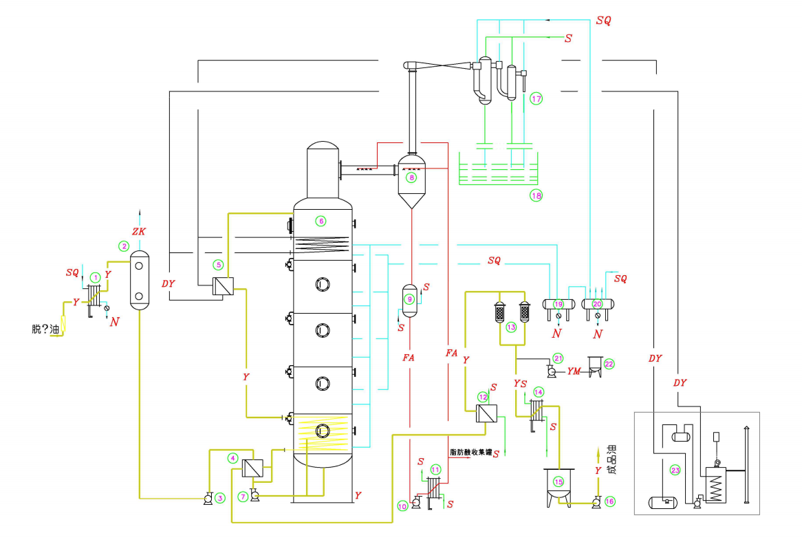
Decolorized oil, after being filtered through a precision filter, is transferred to a buffer tank. The buffer tank operates under vacuum conditions, and as the oil enters, it is atomized by a spray device to remove trace amounts of dissolved oxygen. From the buffer tank, the oil flows into a vacuum energy saver, where it exchanges heat with oil returning from the deodorization tower. After this heat exchange, the oil is further heated using high-pressure steam before being introduced into the deodorization tower for the deodorization reaction. The deodorization tower is a packed-column design, consisting of three distinct sections: - The top section serves as a fatty acid collection zone, capturing and distilling off free fatty acids. - The middle section features structured packing material, facilitating efficient vapor stripping to remove both odor-causing compounds and residual fatty acids. - The bottom section acts as a thermal decolorization holding zone, designed to break down and eliminate heat-sensitive pigments. As the oil enters the deodorization tower, it’s evenly distributed across the tower’s cross-sectional area. Oil droplets then flow downward through the packed bed, forming a thin film along the extensive surface area of the packing material. Inside the packed column, the oil moves countercurrently against the upward-flowing steam, allowing volatile compounds—such as free fatty acids and other odorous substances—to be efficiently stripped away under the combined effects of vacuum and steam. Compared to traditional tray-based systems, the packed-column design significantly reduces direct steam consumption due to its enhanced counter-current mass transfer efficiency. After vapor stripping, the oil moves from the stripping section into the holding section of the tower, where a controlled amount of steam is introduced. Here, certain heat-sensitive compounds undergo thermal decomposition, aiding in the decolorization process. Simultaneously, unstable oxidation byproducts are broken down, resulting in a more stable final product. The duration of the thermal decolorization process can be precisely adjusted—or even locked at a fixed time—based on the oil flow rate and specific processing requirements. Finally, the deodorized hot oil passes through an energy-saving heat exchanger, recovering waste heat before being cooled to below 60°C, yielding the refined, ready-to-use finished oil product.
Fatty acid recovery >>
To recover free fatty acids and other condensable substances while minimizing pollution and reducing the load on the vacuum system, the gas from the deodorization tower is cooled in a fatty acid collector. As the gas passes through the packing material inside the collector, the fatty acids and other volatile compounds are condensed by the circulating cold fatty acid. The recovered fatty acid distillate accumulates in a storage tank located at the bottom of the collector, and an automatic discharge process is controlled by high- and low-level switches. Meanwhile, the circulating fatty acid distillate is continuously kept at a temperature range of 55–60°C via a fatty acid cooler.
Cryogenic Vacuum System >>
The deodorizing vacuum system utilizes freeze-water surface condensation vacuum technology, where chilled water cools the vacuum gas and injected steam indirectly via a surface condenser. The resulting condensate is collected in a storage tank for recycling. Thanks to the use of low-temperature chilled water as the cooling medium, this system significantly enhances the efficiency of water circulation, capture, and condensation. As a result, the overall system load is dramatically reduced compared to conventional designs, leading to a substantial decrease in steam consumption—and, importantly, a much smaller volume of wastewater generated. This not only improves energy efficiency but also contributes more effectively to environmental protection and sustainability.
Continuous Refining Process Flowchart
—— Alkali Refining Section ——
—— Bleaching Section ——
—— Odor Removal Section ——